The WA8DBW 444.200 Repeater
The Micor
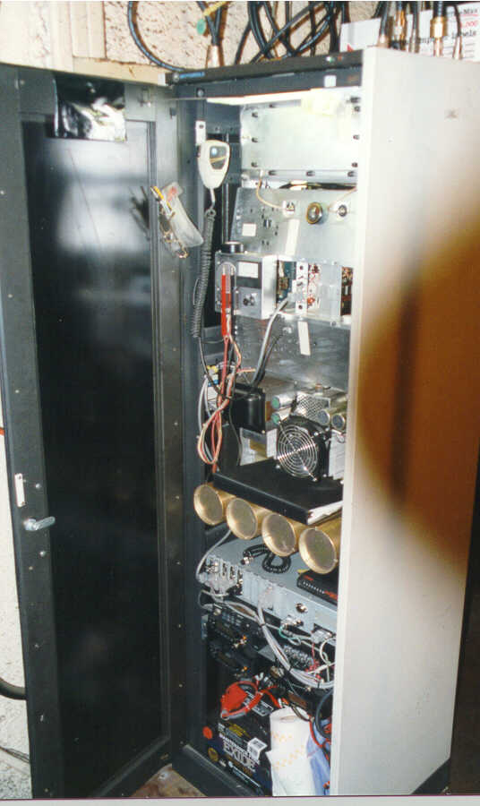
Another view

This is a view of the rear of the exciter -
power amplifier assembly.
The
actual appearance of the repeater is somewhat different than these photos. The
repeater is in a constant state of change. The repeater now has four Kenwood
transceivers for 2, 220. 440.and 1.2 GHz. There also is a HR-2600 for 28 MHz as
well as a modem and additional ports on the controller for two other repeaters.
They can be better viewed on the next page.
At the top is the amplifier heat sink. The amplifier is designed for continuous duty at 75 watts minimum output with no forced air-cooling. Because I dislike trips to the repeater site, I have improved on the design with the addition of two 3 3/4 inch 12 volt DC fans mounted to the heat sink. A third fan is mounted at the top of the cabinet to exhaust the hot air out of the cabinet.
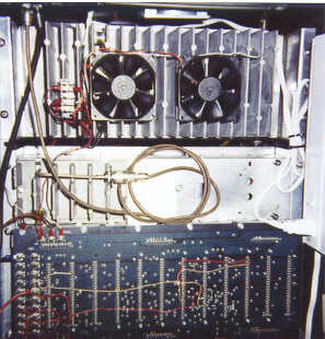
Two sensors on the PA heat sink
thermostatically control the fans. One sensor is mounted in the amplifier
between the four PA transistors. The second sensor is mounted between the fins
of the heat sink. It can be seen in the photograph above the top left corner of
the first fan. This second sensor acts as a backup in the event the internal
sensor should fail. Both are set to turn the fans on at 120 degrees.
A test was made transmitting into a dummy load for 12 hours at 100 watts out. The fans kicked on after 20 minutes. The fans turned off 12 minutes after transmission was stopped. This was done with the room temperature being 68 degrees at the start of the test. At the end of the test the temperature in the shack had increased to 74 degrees. The internal cabinet temperature was 87 degrees. This was up from 77 degrees at the start of the test.
2.3 - 2.4 GHz
If you have one of
these, I will buy it.
This is a TM-2400 for
2400 to 2450 MHz
If you
wish to sell or trade:
Richard D. Reese, WA8DBW 
Last
Update 01/01/99