MICOR
Repeater
Controller
Interface
Richard
D. Reese EN-91 Wadsworth, Ohio
Are
you the proud, even if somewhat bewildered, owner of a Motorola Micor Repeater?
(If you have a MSR-2000, GO HERE ) Are you
scratching your head attempting to figure out the best way to interface your
fancy new controller? Read on, you will find it is really not all that
difficult.
The first thing you must do is verify that your repeater will repeat in its stock form. Failure to do this simple step will only complicate things in the event you have a problem after the modification of the Squelch Gate Card. The modification presented here will enable you to have your fancy external repeater controller (I have an RLC-3) to do just that. Control your repeater. The modification will also, with the flick of a switch, permit the repeater to operate independent of your external controller. This is why you should have started with a "repeating repeater."
Prior
to the modification adjust the squelch key and repeater level to you desired
settings. Set JU-13 to 0 on the Squelch Gate Card. This is the hang timer and
when set to zero it will permit the external controller to determine hang time.
I recommend you at least have the capability of operating the receiver in PL.
In order to do this you must set the two jumpers for PL. These will not be
affected by the interface. Please no more than 5KC deviation. If you have a
Two-Meter machine, use 3.5 to 4 KC deviation. Otherwise those on frequencies
adjacent to yours may not like your system or you! One other thing to remember
is if you have a controller that has speech capability - Set the speech and any
audible tone signaling (DTMF - 2m tone sequential, etc.) for no more than two
thirds system deviation. Your listeners will give you much praise for the
pleasant sounding repeater you have created.
Photograph
of an Unmodified Squelch Gate Card Click Here
Photo
of the card After Modification Click Here
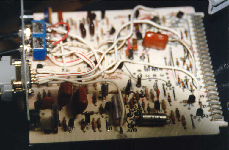
Photo
of the Guts! (Note: DB-9 is close to the edge) Click Here
Photo
of the card After Installation in a MICOR Click Here
The
following is a list of all parts that will be required for the modification:
1
- DB-9 female
1
- 10 K ohm 1/8 watt resistor
1
- Double Pole Double Throw Switch
*
1 - Single Pole Single Throw Switch *
*
If you want a RT disable - an additional SPST switch is required. If you go
this route you will have to drill an additional hole for the mounting of the
switch. The plus is that you can purchase all of the required parts at your
local Radio Shack. The photos show the two-switch version (both DPDT) and that
is what will be described in the article.
Now
on to the modification.
We
will begin with the most difficult. The mounting of the DB-9 socket. Refer to
the photo
showing the relationship of the DB-9 to the edge of the Card front bracket. DO
NOT CENTER THE DB-9! There is not much room for making the hole for the
connector. If you are like me and do not have the hole-punch, or, do not wish
to pay the ridiculous price GREENLEE USA charges, you will have to drill
several holes and file the result to the proper size and shape. If you attempt to center the DB9, you will find you do not
have room to file etc. without hitting components on the PC Board. Next
drill the two holes for the toggle switches. Again be careful so as to prevent
damage to components on the circuit board.
(If
anyone has a punch they wish to sell, Mail Me)
The hard part is now finished. Now the easy part.
1. Mount the switches and the DB-9 with
the appropriate hardware. When finished begin wiring by connecting pins 1,6,8,
& 9 of the DB-9 together.
2. Now run a jumper from pin one to
ground on the board. A convenient place for the ground connection is the
negative end of C 16 a 100 uf 25 volt capacitor. This will be the lead near the
bottom edge of the card about 2.5 inches from the front.
3. Connect a wire from DB-9 pin 2 to
the point where JU-3&4 connect near the top edge of the board about one
inch from the rear of the board. This is the point where the controller gets
its CTCSS Indication.
4. Disconnect the end of JU-12 where it
connects to Pin 18 of the Cards Edge Connector. This is 1.5 inches from the
bottom of the card. Connect this end of the wire to Pin 3 of the DPDT Toggle
Switch for the Internal/External Control selection.
Rear
View of the DPDT Internal/External Control toggle switch.
1
* 4 *
2
* 5 *
3
* 6 *
5. Connect a wire from Pin 1 of the
DPDT Internal/External Control toggle switch to Pin 3 of the DB-9. This is the
PTT for the repeater.
6. From Pin 2 of the DPDT, connect a one-inch
jumper to Pin 1 of the Repeater Transmitter Disable switch.
7. From the spot where the wire (JU-12)
was removed in step 4, (Pin 18 of the cards edge connector) connect a short
wire to Pin 2 of the Repeater Transmitter Disable switch.
8. Connect a wire from Pin 4 of the
DB-9 to Pin 6 of the DPDT Internal/External Control toggle switch. This is
Audio to the Repeater Transmitter.
9. Lift the negative end of C-17 a 4.7
uf capacitor (the lead towards the top of the card) and solder about a
three-inch wire to the negative lead of the capacitor, connect the other end of
the wire to Pin 5 of the DPDT Internal/External Control toggle switch. This is
the processed receiver audio out of the squelch gate card.
10. Connect a jumper from pin 6 of the
DPDT Internal/External Control toggle switch to the point on the card where you
disconnected the negative lead of C 17, the 4.7 uf capacitor.
11. Connect a jumper from Pin 5 of the
DB-9 to Pin 4 of the DPDT Internal/External Control toggle switch. This is the
receiver audio input to the controller.
12. Connect 10K-ohm resistor from Pin 7
of the DB-9 connector to Pin 5 of the cards edge connector. This is the COS
from the repeater receiver for your controller. An easy spot to do this is the
positive or banded end of the second diode from the top of the card. This is
the first one mounted vertically to the left of Pin 9 of the edge connector.
***************************************************************************
If
you have managed to locate a three pole double throw switch with a center off
position then perform the following in place of steps 6 and 7 of the above
instructions.
The
three pole switch must have a center off position. The rear of the switch will
look
like this:
1
* 4 * 7 *
2
* 5 * 8 *
3
* 6 * 9 *
Tie
Pins 7 and 9 together.
In
place of step 6 perform the following:
Connect
pin 2 and pin 7 together.
Next
in place of step 7 perform the following:
From
the spot where the wire (JU-12) was removed in step 4 of the instructions (Pin 18
of the cards edge connector) connect a short wire to Pin 8 of the Repeater
Transmitter Disable switch.
All
of the other steps (1 to 5 and 8 to 12) are as published above.
***************************************************************************
This completes the modification of the
Squelch Gate Card. You should have to make no adjustments to the card if you
set it for proper operation prior to the modification. Set the receiver squelch
to the desired position and that is it. All Transmit and Receive audio level
adjustments will be made in your controller. The connections of the pins on the
DB-9 are as follows:
1 = Ground
2 = PL input from PL Decoder
3 = PTT output from your controller
4 = Transmit audio out from controller
to the repeater transmitter
5 = Audio input to your controller from
the repeater receiver
6 = Ground
7 = Receiver COR output to your
controller
8 = Ground
9 = Ground
These are the same pin-outs as used on
the RLC-3. As a result it will not matter which end of the DB9 cable is plugged
in to the card or the controller.
I have performed this mod to several
Cards and have never had a problem. I welcome your comments and
recommendations. In the event of a problem with the conversion, feel free to
send me e-mail.
If you think the above modifications
are too much effort and you wish to eliminate the factory cards, go to Kevin,
W3KKC's site
and perform his mod. It is outstanding also and some prefer it for its
simplicity.
73 and enjoy.
Remember
that THIS IS A HOBBY. KEEP IT FUN!
TLN4662A
Squelch Gate Module Jumper Table & Board Layout

HOSTED BY ifip.com
Last update 11/19/2011